Calculus with bits and bytes – Part 3: Refined rotary controls
After we did the heavy theory of rotary or circular controls two weeks ago and made a memory efficient proof of concept last week, it’s time to accept that although the standard Gauge component, available for the Basic, Enhanced, and Discovery series, gives us a good base for rotary control experiments, its simplicity limits the use. Not every screen design would accept the 0 value pointing straight towards the left as an ergonomic solution, and allowing a full circle, returning values from 0 to 359 might also not be an appropriate solution everywhere.
Fortunately, the Gauge component in the Intelligent series helps us in creating more ergonomic and realistic solutions. First, it has a .format attribute, which allows us to set the zero point to everywhere in the circle. Second, we have much more control over the visual representation: We can play on the needle’s form and length with the .ws0, .ws1, .ws2, .up, .down, and .hig attributes. Thus, among others with the help of a nice background picture created in Gimp or Photoshop using layers, guides and paths, we may perfectly use a relatively big 200*200px gauge for a comfortable touch control with a 130px diameter rotary button as an indicator.
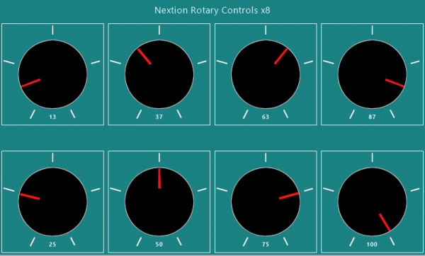
The goal was to achieve more than that: It should look and behave like a classic rotary potentiometer with a rotating angle of 300° and return values from 0 to 100. And yes, as you can see, it’s doable. But before we go into details, please make sure that you have read the two previous blogs linked in the first paragraph, where all the underlying theory and technology is explained.
Step 1: Shifting the zero point
The .format attribute of the Gauge component allows to set the zero point (the position of the needle when the .val attribute is null) to any angle between 0° to 359°. In our case, since we want to represent a rotary potentiometer with a 300° angle, we’d need the needle to travel from -60° to 240° in the Nextion coordinate system, where 0° is straight towards the left. The .format attribute does not accept negative values, so we add 360° and set it to 300. Since the angle calculated from the touch coordinates continues to referring to the initial 0° line, we have to modify our code to do exactly the same, adding 360° and subtracting the .format value from the calculated angle, before we set the gauge’s .val attribute. With this, the touch coordinates and the needle are again in sync.
Step 2: Limiting the rotation
In this project, we decided to limit the rotation angle to 300°. This is done by a simple if – then clause added to the code. But it requires an additional variable to hold the unlimited value. Fortunately at this point, the quot variable is not longer required and can be reused for this purpose.
Step 3: Scaling the result
As we want values from 0 to 100 instead of the 0 to 300 angle value, again, some scaling is done in the code, by adding 1 to the gauge’s .val before dividing it by 3. The added one reduces rounding errors of the integer division.
Put everything together in the code
Since we were smart from the beginning and we centralized the code for an arbitrary number of gauges on the screen, there is only one place where we have to insert our little modifications: at the very end of timer .tm0‘s event code. The latter grows to 31 lines (comments and parentheses including) which is still very compact and efficient code. The modifications and additions to last weeks basic version are printed in bold:
// Calculate the touch coordinates relative to the center:
Xr.val=tch0-Xc.val
Yr.val=tch1-Yc.val
// Calculate the signs:
Sx.val=Xr.val>>31<<1+1 Sy.val=Yr.val>>31<<1+1
// Replace the coordinates by their absolute values:
Xr.val*=Sx.val
Yr.val*=Sy.val
// Compute the angle using segmentation and approximation:
if(Yr.val>=Xr.val)
{
  quot.val=Xr.val<<8/Yr.val
  Xr.val=90*Sy.val+180 // reuse the Xr variable to store the offset
  Yr.val=-1*Sx.val*Sy.val // reuse the Yr variable for intermediate result sign
}else
{
  quot.val=Yr.val<<8/Xr.val
  Xr.val=-90*Sx.val+270 // reuse the Xr variable to store the offset
  Yr.val=Sx.val*Sy.val // reuse the Yr variable for intermediate result sign
}
atan.val=256-quot.val*4009+2949120*quot.val+8388608>>24
// add the sign and offset to the approximation result, normalize, reusing the quot variable
quot.val=atan.val*Yr.val+Xr.val+360-b[tc0.val].format%360
if(quot.val>300) // limit the range and position the needle accordingly
{
  b[tc0.val].val=300
}else
{
  b[tc0.val].val=quot.val
}
b[tc0.val+1].val=b[tc0.val].val+1/3 // scale and update the associated number component
Conclusion
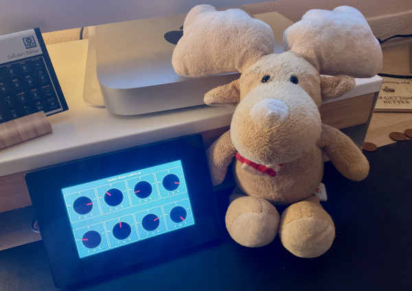
If your project is well thought from the beginning, further extensions can be brought in relatively easily. And in today’s demo project, we have a huge benefit from centralizing the code: We may have 8 touch sensitive rotary knobs on one page which all automatically “inherit” the few code extensions made in one single place.
Now, I let you play with it. Have fun, turning the knobs by touching your Nextion HMI or playing with it in the simulator: rotary_controls.HMI
Do you wonder why we made such an important point on circular controls ? Your guesses are welcome by email! 👇
Last, but not least
You have any questions, comments, critics, or suggestions? Just send me an email to thierry (at) itead (dot) cc! 🙂
And, by the way, if you like and you find useful what I write, and you are about to order Nextion stuff with Itead, please do so by clicking THIS REFERRAL LINK! To you, it won’t forcibly make a change for your order but on some products, you may even get a 10% discount using the coupon code THIERRYFRSONOFF. In ever case, it will pay me perhaps the one or the other beer or coffee. And that will motivate me to write still more interesting blogs 😉
Thank you for reading and happy Nextioning!